Electronics Projects On Breadboard Using 555 Timer IC
A collection of easy to make electronics projects on breadboard using 555 timer IC. Each project includes step by step instructions on how to build the circuit along with explanations of how the circuit works.
List of Electronics Projects on Breadboard Using 555 Timer IC
Touch On-Off Sensor Switch Circuit Using 555 Timer IC
A tutorial on how to make a Touch On and Touch Off sensor switch using 555 timer IC on a breadboard. This circuit uses two pairs of touch conductors to sense and register the touch.
Latching Touch Sensitive Alarm Circuit Using 555 Timer IC
A tutorial on how to make a touch sensor alarm circuit using 555 timer IC on a breadboard. It consists of a touch sensor (made up of conductive material like copper wire) which when touched by our skin or any object with electric charge, activates the buzzer alarm connected at the output of 555 timer IC.
Piezo Electric Knock On-Off Sensor Switch Circuit Using 555 Timer IC
A tutorial on how to make a Tap On Tap Off piezoelectric knock sensor circuit using 555 timer IC on a breadboard. This circuit toggles (flip-flops) the output each time we tap on the Piezo-Electric speaker.
Adjustable Auto On Off Delay Timer Circuit Using 555 IC
A tutorial on how to make an adjustable delay timer circuit using 555 IC that can automatically turn on/off any output after a fixed duration. This electronic timer circuit is helpful when you need to power On/Off any AC Appliances after a pre-defined duration.
Adjustable Flashing/Blinking LED Circuit using 555 Timer IC
A tutorial on how to make an Adjustable Flashing/Blinking LED circuit using 555 timer IC and a few other electronic components. This circuit toggles an LED or any output device ON and OFF at regular intervals of time.
Tick Tock Sound Generator Circuit using 555 Timer IC
A tutorial on how to make a ticking sound generator circuit using 555 timer IC. The sound feels similar to the one used when showing a ticking time bomb in movies. A reverb container can be added over the speaker to make it sound similar to the tick tock audio emanated from mechanical clocks.
Machine Gun Sound Generator Circuit Using 555 IC
A tutorial on how to make a Machine Gun Sound generator circuit using 555 timer IC and a few other electronics components. This circuit simulates sound similar to the audio emitted from continuous triggering of a machine gun.
Light Screamer Circuit Using LDR and 555 Timer IC
A tutorial on how to make a light screamer circuit using LDR (Light Dependent Resistor) and 555 timer IC. This circuit generates a screaming noise depending on the amount of light incident on the LDR/Photocell.
DIY Electric Piano Circuit using 555 timer IC
A tutorial on how to make an Electronic Piano circuit using 555 timer IC and a few other electronics components. This circuit consists of a number of push button switches (similar to different keys in a piano) which, when pressed, produce sounds with different tones via a speaker.
Wailing Siren Circuit Using 555 IC
A tutorial on how to make a wailing siren circuit using 555 timer IC on a breadboard. This circuit can be triggered by pressing a push button switch and it produces a tone with increasing intensity for as long as push button is pressed.
LED Dimmer and DC Motor Speed Controller Circuit Using PWM Technique
A tutorial on how to make a PWM (Pulse Width Modulated) controller circuit for controlling the speed of DC Motors and brightness of LED’s. This circuit uses 555 timer IC to generate continuous ON-OFF pulses which control the speed of DC motors or brightness of LED’s.
Servo Motor Controller and Tester Circuit Using 555 IC
A tutorial on how to make a servo motor controller & tester circuit using 555 timer IC and a few other components. This circuit allows us to manually drive/control any servo motor by pressing buttons or by turning knob of a potentiometer.
Police Lights Themed Flashing LED Circuit Using 555 IC
A tutorial on how to make a Police Lights themed LED Flashing/Blinking LED circuit using 555 timer IC and a few other electronics components. This circuits alternatively flashes between Red LED’s and Blue LED’s while blinking each of them individually similar to police strobe lights.
Police Siren Circuit Using 555 IC
A tutorial on how to make a police siren circuit using 555 timer IC and a few other electronics components. This circuit smoothly transitions the output sound between two different tones/frequencies, similar to the sound emitted from police cars.
Model Traffic Lights Circuit Using 555 IC
A tutorial on how to make a model traffic lights circuit using 2 555 timer IC’s and a few other electronics components. This circuit turns ON green LED, keeps it ON for some time, then turns ON yellow LED for a moment and finally turns ON red LED for almost the same duration as the green LED.
Light Sensor and Darkness Detector Circuit Using LDR + 555 IC
A tutorial on how to make a light sensor circuit plus darkness detector circuit using 555 timer IC and a few other electronics components. When this circuit is configured as a light sensor circuit, it turns ON the output whenever light around the LDR is more than a certain amount (threshold).
Fastest Finger First Circuit using 555 IC For Organizing Quizzes
A tutorial on how to make a fastest finger first circuit which can track the first person to press the trigger or Buzzer. This circuit consists of multiple replicas of a module, each of which can be assigned to a single quiz taker or a team.
Light Sensor Circuit Using LDR and 555 Timer IC with Adjustable sensitivity
In this tutorial we’ll learn how to make a light sensor circuit using LDR (Light Dependent Resistor), 555 timer IC and a few other electronics components. This circuit detects light incident on the LDR and turns on LED whenever the intensity of light is greater than a certain level.
DC Voltage Doubler Circuit Using 555 Timer IC
A tutorial on How to make a DC Voltage Doubler Circuit on breadboard using 555 Timer, Diodes & Capacitors. This circuit takes in a DC voltage anywhere between 5V to 15V and produces double the input voltage at the output.
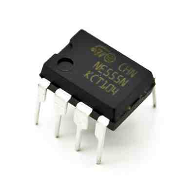
ST DIP 555 Timer IC, For Electronics
Introduction the 555 timer ic is an integrated circuit (chip) used in a variety of timer, pulse generation, and oscillator applications. The 555 can be used to provide time delays, as an oscillator, and as a flip-flop element. Derivatives provide up to four timing circuits in one package application precision timing pulse generation sequential timing time delay generation pulse width modulation.

About the Company
Year of Establishment 2016 Legal Status of Firm Individual - Proprietor Nature of Business Manufacturer Number of Employees Upto 10 People Annual Turnover Rs. 1 - 2 Crore IndiaMART Member Since Jun 2018 GST 07BTGPK3625R1Z5 Import Export Code (IEC) BTGPK*****
The company was incorporated with small group of highly qualified technocrats with sound business acumen and strong technical skills. We are empowered with state-of-the-art infrastructural facilities and highly skilled workforce. Our in-house technocrats are expert in multiple fields and highly experienced that required to run the modern business. We are now focusing on progressively increasing our customer list as well as holding soft wares to significantly enhance the performance and building market leadership.
Company Video
Introducing 555 Timer IC – Tutorial
In this blog post, we will introduce the 555 Timer Integrated Circuit (IC). You’ll explore what it is, the three different modes and its pinout.

555 Timer (EN555)
The 555 timer is an integrated circuit, it is extremely versatile and can be used to build lots of different circuits.
The EN555 is usually used to generate continuous series of pulses. These series of pulses allow you to continuously blink an LED, for example.
The 555 timer can operate in three different modes:
Monostable mode: usually used to create time delays
usually used to create time delays Astable mode: outputs an oscillating pulse signal
outputs an oscillating pulse signal Bistable mode: the 555 timer changes its output depending on the state of two inputs
In this post, you’ll see an example in astable mode.
Pinout
If you search on Google 555 timer datasheet, one of the first results should be a PDF datasheet.
This is a document with a lot of information, but what you really need to pay attention right now is to the pinout. Here’s the EN555 pinout:
This IC has 8 pins:
Ground Trigger Output Reset Control Voltage Threshold Discharge VCC
In a circuit diagram, usually the 555 timer is drawn as follows:
Output
Pin 3 is the output. This pin generates an oscillation. The voltage is high, then low, then high, then low again and so on (this is called astable mode).
Astable mode
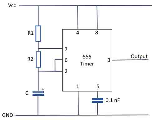
To make the 555 timer work in astable mode, you should wire your circuit like this:
The frequency of the oscillation can be adjusted by changing the values of the resistors R1 and R2 and the capacitance of the capacitor C.
The frequency can be calculated using the following expression:
With the output voltage that comes from pin 3, you can control anything you want (like an LED, speaker, motor, etc.).
Flashing an LED with the 555 Timer
In this section, you will flash an LED using the 555 timer in astable mode. So, we just need to add an LED to the output of the previous circuit.
Required components
These are the components you’ll need:
You can use the preceding links or go directly to to find all the parts for your projects at the best price!
Circuit diagram
This is the circuit diagram:
Wiring the circuit
You can either follow the previous schematic or follow the breadboard wiring diagram below. Finally, power up your circuit by connecting the battery to your breadboard:
In the end, you should see your LED blinking like this:
Note: replace your 1uF electrolytic capacitor with another capacitor that has a lower capacitance and see the LED flashing at a different rate. With lower capacitance values, the flash rate increases.
Wrapping up
I hope you’ve learn something new today and you’ve found this explanation useful.
If you’d like to know more about electronics basics or if you’d like to start into the world of electronics make sure you check out our Electronics for Beginners eBook.
Thanks for reading!
Comments